

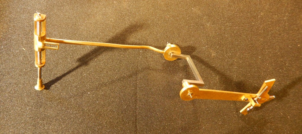
This clock has been causing a few headaches! It runs it doesn’t run, it runs it doesn’t run, the escape wheel is approximately 12 mm dia, it is a lever detent escapement, the escape wheel impulses directly onto an arm attached to the crutch (the top end shown above with the pallet engaged with the escape wheel).
The whole crutch assembly is shown below.
The escape wheel is powered by a Gravity remontoire, however there seems to be uneven power getting to the escapement and at times not enough to run the clock.

These videos show how different the escapement can be adjusted the bottom one shows a more desirable action of the escapement but it would still not consistantly keep the clock running.
On doing some testing it has become evident that there is a problem with the pendulum and crutch.
If the pendulum is left to free swing with out the crutch attached it will maintain a reasonable swing for around 25 to 30 minutes, however as soon as the crutch is put in place and attached to the pendulum the free swing time drops to around 6 minutes, I now have to find a set up that the pendulum and crutch together will maintain momentum for longer than the current 6 minutes.
This project is an ongoing job, I will update as I go along.
Since the last post gears have been turning slowly, here is a video of the movement in various states of adjustment, in this video I have done a slight modification to the crutch and the clock runs more consistantly than before
I recently set up a simple test to get a Q factor amount for the pendulum.
I used a Microset timer in count mode using the optical sensor to count the oscillations and offset the sensor to stop counting as the pendulum got down to around 37% of its swing.
Earlier I had done a similar test but only t check decay of the swing, this time I started with a smaller swing, the total arc being close to 40 mm(20mm each side of the centre).
With the, MODIFIED crutch free swinging the time to degrade to 37% of its swing was 11 mins
Without the crutch attached the time taken was 52 mins.
This is telling me that there is a huge loss of energy with the crutch attached, however the clock is now running where as before it struggled.


Above are a couple of images one before and one after of the change that I have made so this clock will run a bit more consistantly, spot the difference
timing on the final set up was telling me -5.3 sec a week with an instability of 1 sec a day.

I think it is time to move onto another project…..
This clock has reared it’s head again the customer is having problems with it, it won’t run again, I will go and have another look once the Covid restrictions have been eased
